catalyst.passes.parity_synth
- parity_synth(qnode)
Pass for synthesizing phase polynomials in a circuit.
ParitySynth has been proposed by Vandaele et al. in arXiv:2104.00934 as a technique to synthesize phase polynomials into elementary quantum gates, namely
CNOTandRZ. For this, it synthesizes the parity table of the phase polynomial, and defers the remaining parity matrix synthesis to RowCol.Note
This transform requires decorating the workflow with
qjit(). Additionally, this pass requires thenetworkxpackage, which can be installed viapip install networkx.- Parameters:
fn (QNode) – QNode to apply the pass to
- Returns:
This pass walks over the input circuit and aggregates all
CNOTandRZoperators into a subcircuit that describes a phase polyonomial. Other gates form the boundaries of these subcircuits, and whenever one is encountered the phase polynomial of the aggregated subcircuit is resynthesized with the ParitySynth algorithm. This implies that while this pass works on circuits containing any operations, it is recommended to maximize the subcircuits that represent phase polynomials (i.e. consist ofCNOTandRZgates) to enhance the effectiveness of the pass. This might be possible through decomposition or re-ordering of commuting gates.Note that higher-level program structures, such as nested functions and control flow, are synthesized independently. I.e., boundaries of such structures are always treated as boundaries of phase polynomial subcircuits as well. Similarly, dynamic wires create boundaries around the operations using them, potentially causing the separation of consecutive phase polynomial operations into multiple subcircuits.
Example
In the following, we apply the pass to a simple quantum circuit that has optimization potential in terms of commuting gates that can be interchanged to unlock a cancellation of a self-inverse gate (
CNOT) with itself. Concretely, the circuit is:import pennylane as qp dev = qp.device("lightning.qubit", wires=2) @qp.qjit(capture=True) @qp.transforms.parity_synth @qp.qnode(dev) def circuit(x: float, y: float, z: float): qp.CNOT((0, 1)) qp.RZ(x, 1) qp.CNOT((0, 1)) qp.RX(y, 1) qp.CNOT((1, 0)) qp.RZ(z, 1) qp.CNOT((1, 0)) return qp.state()
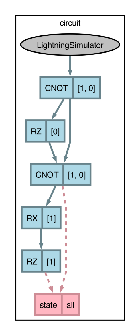
We can draw the circuit and observe the last
RZgate to be wrapped in a pair ofCNOTgates that commute with it. Before the pass is applied:>>> fig, ax = catalyst.draw_graph(circuit, level=0)(0.52, 0.12, 0.2) >>> fig.savefig('path-to-file.png', dpi=300, bbox_inches='tight')
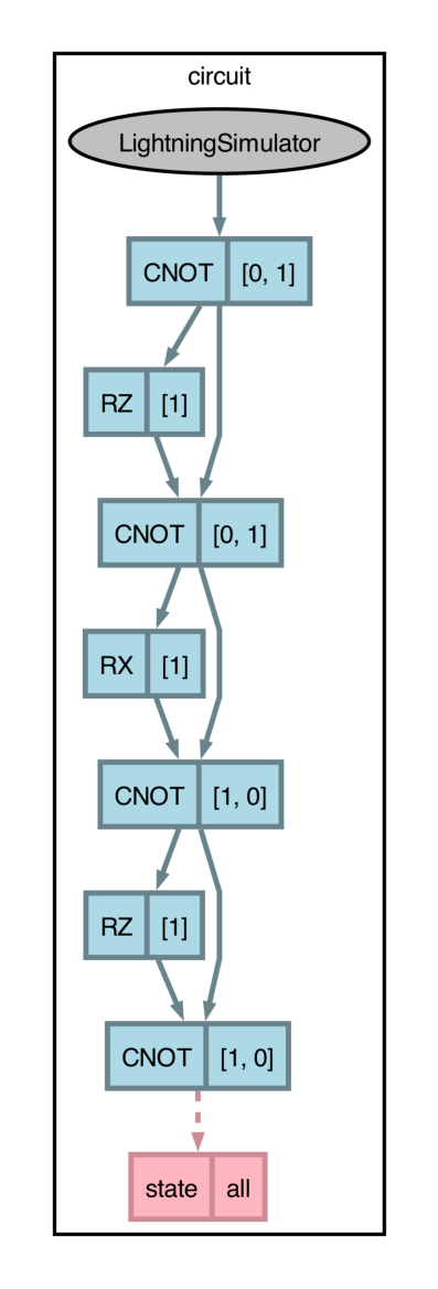
After the pass is applied:
>>> fig, ax = catalyst.draw_graph(circuit, level=1)(0.52, 0.12, 0.2)
>>> fig.savefig('path-to-file.png', dpi=300, bbox_inches='tight')